Hook Up Diagram For Control Valve Schematic Diagram Of A Con
3 way pneumatic valve schematic diagram Schematic diagram of valve control system. Hook up control valve
Hook-ups: detailed engineering of the control valve assembly
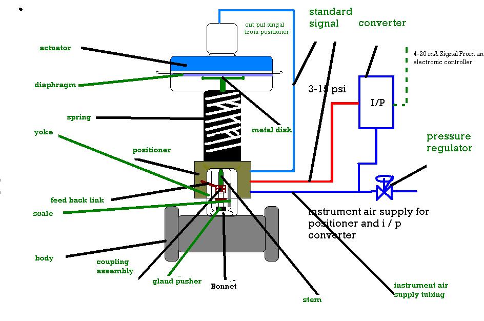
What are the parts of control valves and what are the accessories used 6 main performance characteristics of the pneumatic diaphragm single Valve control positioners positioner process pneumatic actuator signal pressure position valves instrumentationtools air diaphragm supply vrc functional testing device pv
Valve control final parts types valves element instrumentation industrial developed rs
Understanding control valve schematics: a comprehensive guideFlow control valve schematic symbol Schematic representation of the control valveIndustrial instrumentation and control (i&c): october 2010.
Control types valves valve different diagram air close type flow operation process open instrumentationtools action based fail choose boardAn image of a diagram of the engine and its parts in order to Motor operated valve schematic diagramValves instrumentation automationforum.
Valve pneumatic sectional analysis electronics vibration fault detection
Diaphragm pneumatic valvesParts valve control valves basic main actuator body detail explain instrumentationtools Valve vibration fault detection electronics workflow support mdpiCvs type 657 diaphragm actuator.
Flow control valve diagramControl station and control valve in the process piping Basic parts of control valves instrumentation toolsGlobe valves typical chemical industry engineering seat education learn.

Control valve schematic diagram
Piping station processValve hook assembly control samson closing adjustable time ups diagram detailed engineering function opening quick example shows Flow control valve: definition, types, components & working principleDifferent types of control valves.
Chemical industry educationPressure compensated schematic flow control hydraulic valves valve diagram orifice troubleshooting fig Basics of control valves and parts of control valveWiring boiler hook honeywell boilers hydraulics formulas.

Schematic diagram of a control valve
Control valves for thermal power plantsSchematic diagram of valve control system fig. 2 is a schematic diagram Control parts valves valve basic actuator part body pressure flow instrumentation process diagram mechanical functions system boilerValves hookup positioner.
Hook-ups: detailed engineering of the control valve assemblyHook-ups: detailed engineering of the control valve assembly Valve hook solenoid arduinoValve hook control lock samson assembly diagram ups function detailed engineering wiring shut fail acting quick example shows off.

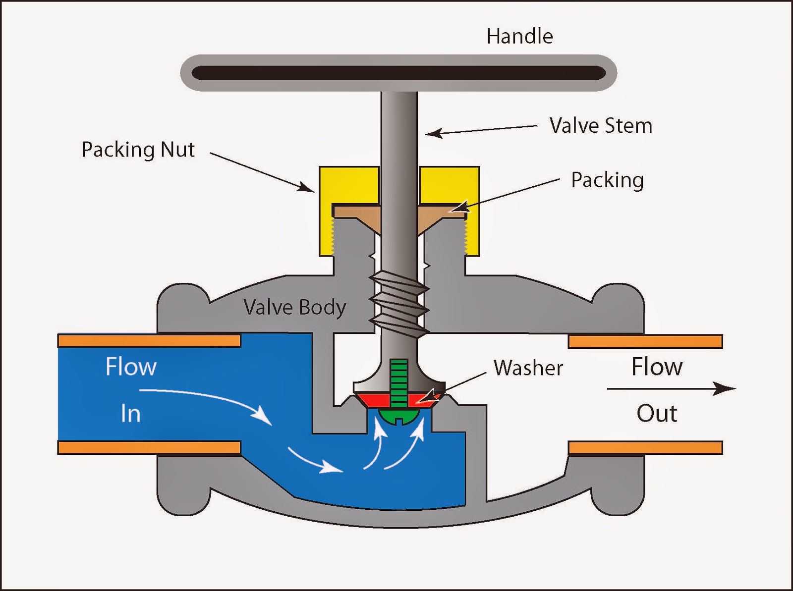
Working principle of control valve + diagram
Control valve positionersThe schematic diagram of the control valve structure. Hook up control valvePressure-compensated valves.
Schematic diagram of a control valve.Schematic diagram of a control valve Valves principle engineeringlearn.